Procedure for the verification of tolerances
Once the manufacture of any part in the workshop has been completed, it is necessary to check that its dimensions comply with the tolerances specified in the drawings. There are two ways of verifying the dimensional tolerances of any part:
- Indirect measurement: in this case, different methods and instruments can be used, the most common being gauges or fixed gauges.
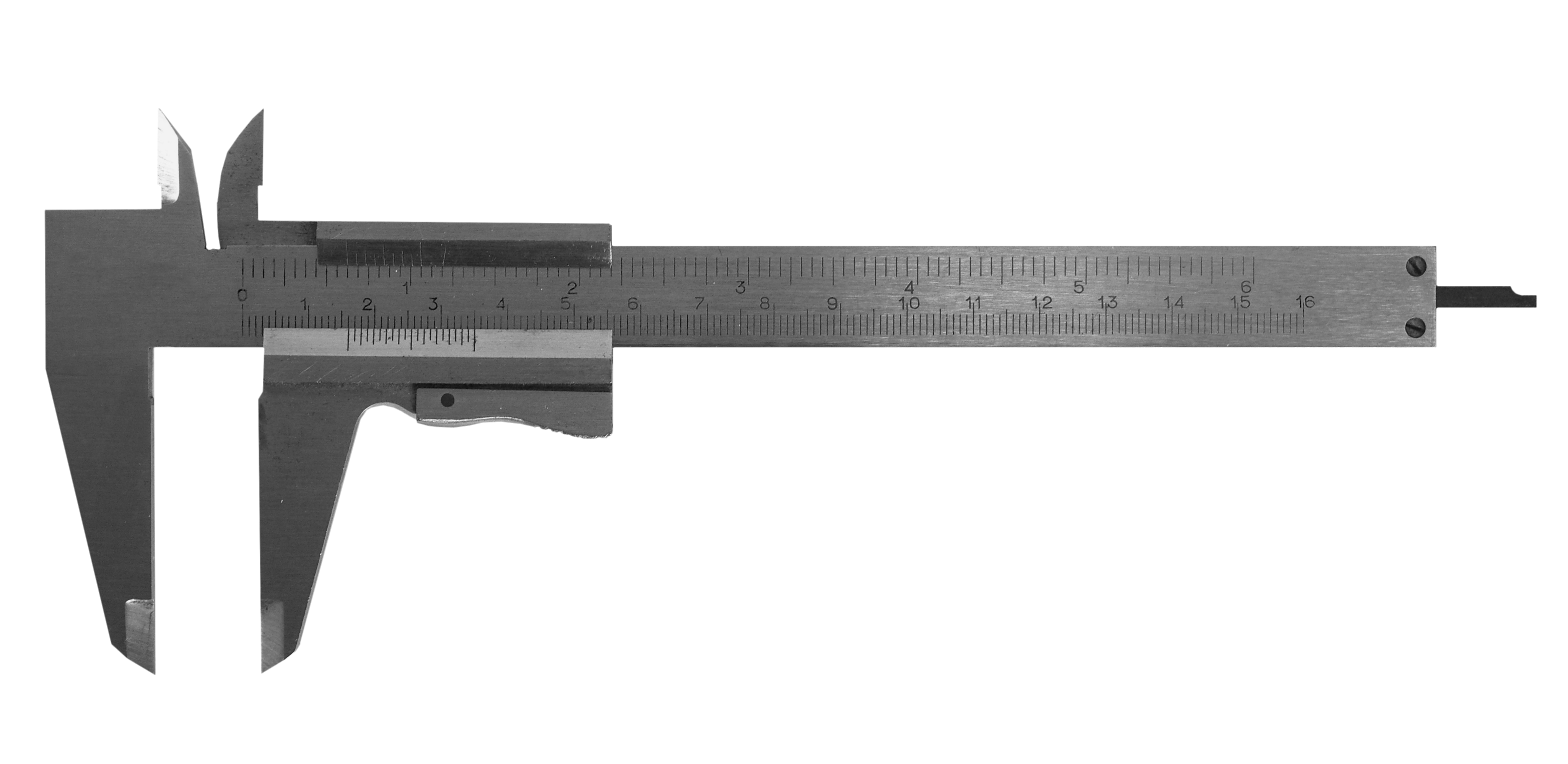
- Direct measurement: in this procedure, micrometers are generally used, the tips of which are adapted to be inserted into the flank of the threads.
Of the above, the most common is the use of gauges or fixed gauges. These instruments are used for the verification of serial parts that must keep a certain measurement within the permitted tolerances.
It is important to emphasise that in the work area where the measurement checks are carried out, the ambient temperature must be regulated to 20 ºC so that the measurement is not altered by the possible expansion of the part to be checked.
Quality of tolerances
Dimensional tolerances take into account the quality of the part. The quality or quality index is a set of tolerances corresponding to the same degree of precision for any group of diameters. The higher the quality of the part, the lower the tolerance, and the lower the quality index.
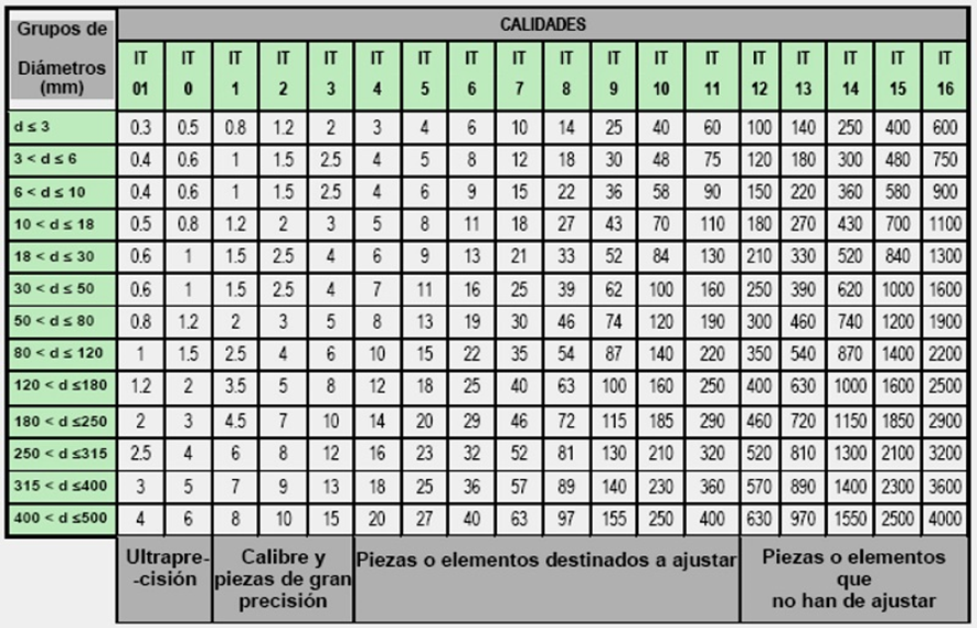
The ISO standard distinguishes eighteen grades designated as IT01, IT0, IT1, IT2, IT3..., for nominal dimensions between 0 and 500 mm, with the higher the number associated with the designation, the lower the quality grade. In this way, the following main groups of grades can be distinguished:
- Grades 01 to 3 for shafts, and 01 to 4 for bores, are used for the manufacture of gauges and high-precision parts.
- Grades 4 to 11 for shafts and 5 to 11 for bores are intended for parts to be adjusted.
- Finally, grades above 11 are used for isolated parts or elements that do not require such a fine finish.
The following table shows the fundamental values in microns (µm) for each of the eighteen grades and for each of the thirteen dimension groups of the main series:
DIMENSIONAL TOLERANCE
ISO 2768 1:1989 Standard Tolerance Tolerance General dimensions.
Tolerance quality
In terms of tolerance quality we can say that the higher the quality, the lower the tolerance.
The ISO system foresees 18 qualities designated by: IT01, IT-0,...., IT-16,
As general applications we could mention the following:
QUALITIES APPLICATIONS
IT-01 - IT-5 Construction of control instruments and in high precision mechanics.
IT-6 - IT-11 In precision mechanics and for mechanical adjustment in general.
IT-12 - IT-16 In coarse fabrication work and parts such as castings, forging, etc.
The higher the quality, the smaller the permissible tolerance; on the other hand, experience shows that it is easier to obtain a tolerance of 5µm on a 50mm diameter than on a 400mm diameter. It follows that the width of the tolerance zone will depend on:
- The quality to be assigned.
- The dimension to be obtained.
GEOMETRIC TOLERANCE
ISO 1101:1983
ISO 8015:2012
In certain cases, e.g. very precise mechanisms, large or very small parts, etc., the specification of dimensional tolerances may not be sufficient to ensure correct assembly and operation of the mechanisms. Figure 1.1 shows three cases where one of the parts may be correct from the dimensional point of view (section diameters within tolerance) and not be suitable for assembly: in the first case we would have a straightness defect, in the second case we would have a coaxiality defect, and in the third case we would have a perpendicularity defect.
In manufacturing, geometric irregularities occur that can affect the shape, position and orientation of the different constructive elements of the parts. A dimensional tolerance applied to a measurement exercises some degree of control over geometric deviations. For example: dimensional tolerance has an effect on parallelism and flatness. However, sometimes the measurement tolerance does not sufficiently limit geometrical deviations; therefore, in these cases a geometrical tolerance must be explicitly specified, taking precedence over the geometrical control already implicit in the dimensional tolerance. The geometric tolerance controls the shape, position or orientation of the elements to which it applies, but not their dimensions, in other words we could define the geometric tolerance of an element, part, surface, axis, plane of symmetry, etc. as the tolerance zone within which the element must be contained. Within the tolerance zone the element can have any shape or orientation, unless some more restrictive indication is given.
FAILURES IN ISO STANDARDS FOR GEOMETRICAL TOLERANCES.
The functional definition of parts leads to solving problems not addressed by ISO standards, e.g. determining the radii of agreement of concave fillets or establishing references on surfaces not identified by ISO standards. The problems encountered by the designer are outlined and possible solutions to these problems are proposed. Keywords: radii of agreement, concave roundings, references, functional requirements.
The first problem lies in the determination of concave roundings.
The resistance to both bending and torsional stresses of parts of revolution is very sensitive to shape defects and particularly to sudden variations in cross-section. In the theory of mechanical design, it is shown that it is necessary to apply stress concentration coefficients, depending on the value of the radii of agreement of the concave roundings. In the determination of these coefficients it is assumed that the concave rounding is perfectly tangent to the neighbouring surfaces.
In industrial practice, these roundings are also defined by allowing a tolerance in the value of the radius of curvature of the rounding, and expressed as shown in the figure. This form of definition coincides with mechanical design theory in taking the radius as a parameter. This form of definition, of the dimensional tolerance type, is not authorised by ISO 8015, which reserves this type of definition for cylindrical elements or elements bounded by parallel planes.
ISO 1101, relating to geometric tolerances, makes it possible to define, for any curves and surfaces, a tolerance zone within which the element affected by the shape tolerance must be located.
MEANING GEOMETRIC TOLERANCES. TYPES.
1. Straightness tolerance
(a) When the tolerance zone is projected onto a plane, it is bounded by two parallel lines separated by a distance -t-.
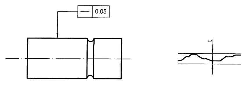
Figure 1
Any line in the area indicated by the tolerance rectangle must lie between two parallel lines equidistant 0,05 mm.
(b) The tolerance zone is a cylinder of diameter -t-, provided that the tolerance value is preceded by the sign Ø.

Figure 2Figure 2. The axis of the component indicated by the tolerance rectangle must lie inside a cylinder of diameter 0,08 mm.
Flatness tolerance
The tolerance zone is limited by two parallel planes separated by a distance -t-.
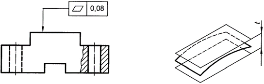
Figure 3
Figure 3. The upper surface of the part shall be between two parallel planes 0,08 mm apart.
Roundness tolerance
The flat tolerance zone is bounded by two concentric circles spaced -t- apart.
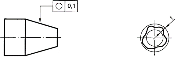
Figure 4
The circumference of any orthogonal section must lie between two concentric coplanar circles 0,1 mm apart.
4. Cylindricality tolerance
The tolerance zone is bounded by two coaxial cylinders with a difference between radii -t-.
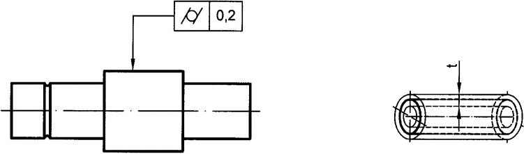
Figure 5
Figure 5. The area marked by the tolerance rectangle must be between two coaxial cylinders with a radius difference of 0,2 mm.
5. Shape tolerance of a line
The tolerance zone is bounded by the two envelopes of circles of diameter -t-, with their centres on a line having the perfect geometrical shape.
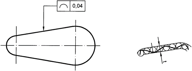
Figure 6
In each section parallel to the projection plane in which the tolerance is specified, the controlled profile must remain within the specified tolerance zone, which is bounded by the two envelopes of circles of diameters 0,04 mm, the centres of which lie on a geometrically perfect profile.
6. Shape tolerance of a surface
The tolerance zone is bounded by the two enveloping surfaces of spheres of diameter -t-, with their centres lying on a geometrically perfect surface, defined with theoretically exact dimensions.
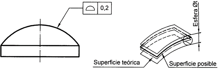
Figure 7
Figure 7. The controlled surface must be contained between the two enveloping surfaces of 0,2 mm diameter spheres, the centres of which lie on a geometrically perfect surface.
7. Parallelism tolerance
a) The tolerance zone is defined by two planes parallel to each other and to the reference plane, separated by a distance -t-.

Figure 8
The top surface of the component must lie between two planes parallel to each other and to the reference surface A, spaced 0,1 mm apart.
(b) The tolerance zone is defined by a cylinder of diameter -t- with axis parallel to the reference, when the tolerance value is preceded by the sign Ø.
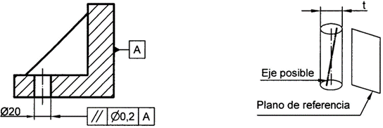
Figure 9
Figure 9. The axis of the bore indicated by the tolerance rectangle must lie within a cylinder of diameter 0,2 mm, parallel to the reference surface A.
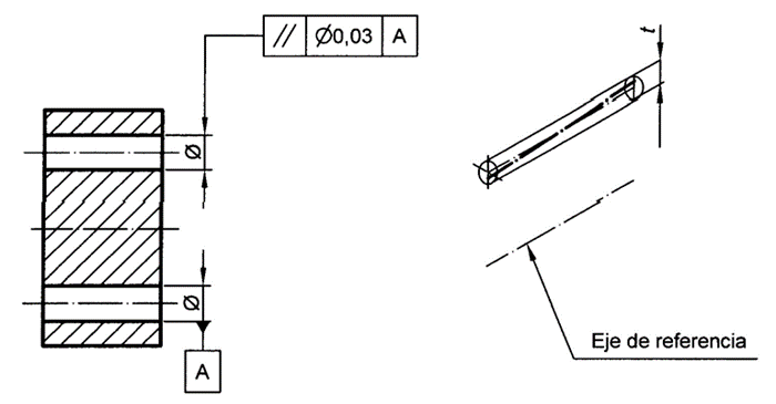
Figure 10
Figure 10. The axis of the bore indicated by the tolerance rectangle must be inside a cylinder of diameter 0,03 mm, parallel to the reference line A.
8. Perpendicularity tolerance
(a) The tolerance zone is bounded by a cylinder of diameter -t-, with axis perpendicular to the reference plane, when the tolerance value is preceded by the sign Ø.
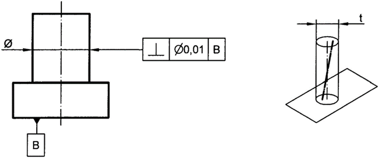
Figure 11
Figure 11. The axis of the controlled cylinder, the upper cylinder, must lie within a cylindrical tolerance zone of diameter 0,01 mm, and axis perpendicular to the reference plane B.
b) The tolerance zone is defined by two planes parallel to each other, perpendicular to the reference plane and separated by a distance -t-.
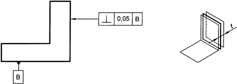
Figure 12
Figure 12. The area indicated by the tolerance rectangle must lie between two planes parallel to each other, spaced 0,05 mm apart, and perpendicular to the reference plane B.
9. Tilt tolerance
The tolerance zone is bounded by two parallel planes spaced -t- apart and inclined at the specified angle to the reference plane.

Figure 13
Figure 13. The inclined plane of the part must be between two planes parallel to each other, spaced 0,1 mm apart, and inclined at an angle of 25° to the reference plane A.
10. Position tolerance
The tolerance zone is limited by a cylinder of diameter -t-, the axis of which is at the exact theoretical position of the controlled straight line, when the tolerance value is preceded by the sign Ø.

Figure 14
Figure 14. The axis of the bore must be inside a cylindrical tolerance zone of diameter 0,05 mm, the axis of which is at the exact theoretical position in relation to the reference planes C and D.
11. Coaxiality tolerance
The tolerance zone is limited by a cylinder of diameter -t-, the axis of which coincides with the reference axis, when the tolerance value is preceded by the sign Ø.
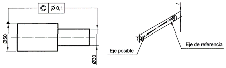
Figure 15
Figure 15. The axis of the cylinder indicated by the tolerance rectangle, the right one, must be inside a cylindrical tolerance zone of diameter 0,1 mm, coaxial with the reference axis, the left one.
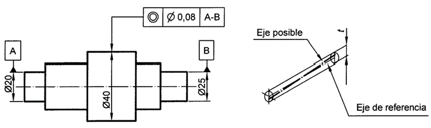
Figure 16
Figure 16. The axis of the cylinder indicated by the tolerance rectangle, the centre one, must lie within a cylindrical tolerance zone of diameter 0,08 mm, coaxial with the reference axis A-B.
12. Symmetry tolerance
The tolerance zone is bounded by two parallel planes spaced -t- apart and placed symmetrically with respect to the reference symmetry plane (or axis).

Figure 17
Figure 17. The plane of symmetry of the slot must be contained between two parallel planes spaced 0,025 mm apart and placed symmetrically with respect to the plane of symmetry specified by reference A.
13. Circular oscillation tolerance (radial)
The tolerance zone is limited, within any plane of measurement perpendicular to the axis, by two concentric circles of radius difference -t- and centre coincident with the reference axis.
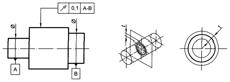
Figure 18.
Figure 18. The radial oscillation tolerance must not exceed more than 0,1 mm in any measuring plane, during one complete revolution, about the reference axis A-B.
14. Total oscillation tolerance (radial)
The tolerance zone is limited by two coaxial cylinders of radius difference -t-, whose axes coincide with the reference axis.
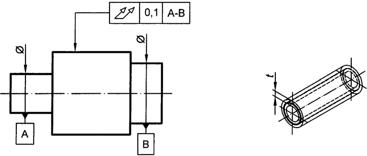
Figure 19
Figure 19. The total radial oscillation tolerance must not exceed 0,1 mm, at any point on the specified surface, during several revolutions about the reference axis A-B, and with relative axial movement between the part and the measuring instrument.
15. Straightness tolerance
(c) When the tolerance zone is projected onto a plane, it is bounded by two parallel lines spaced -t- apart.
Figure 1
Any line in the area indicated by the tolerance rectangle must lie between two parallel lines equidistant 0,05 mm.
(d) The tolerance zone is a cylinder of diameter -t-, provided that the tolerance value is preceded by the sign Ø.
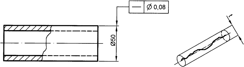
Figure 2
Figure 2. The axis of the component indicated by the tolerance rectangle must lie inside a cylinder of diameter 0,08 mm.
16. Shape tolerance of a surface
The tolerance zone is bounded by the two enveloping surfaces of spheres of diameter -t-, with their centres on a geometrically perfect surface, defined with theoretically exact dimensions.
Figure 7
Figure 7. The controlled surface must be contained between the two enveloping surfaces of 0,2 mm diameter spheres, the centres of which lie on a geometrically perfect surface.
17. Parallelism tolerance
(c) The tolerance zone is defined by two planes parallel to each other and to the reference plane, separated by a distance -t-.
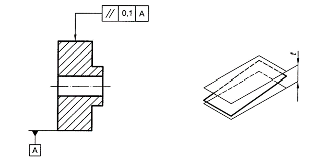
Figure 8
The top surface of the component must lie between two planes parallel to each other and to the reference surface A, spaced 0,1 mm apart.
(d) The tolerance zone is defined by a cylinder of diameter -t- with axis parallel to the reference, when the tolerance value is preceded by the sign Ø.
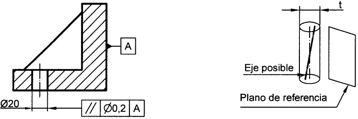
Figure 9
Figure 9. The axis of the bore indicated by the tolerance rectangle must lie within a cylinder of diameter 0,2 mm, parallel to the reference surface A.
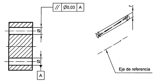
Figure 10
Figure 10. The axis of the bore indicated by the tolerance rectangle must be inside a cylinder of diameter 0,03 mm, parallel to the reference line A.
18. Perpendicularity tolerance
(c) The tolerance zone is bounded by a cylinder of diameter -t-, with axis perpendicular to the reference plane, when the tolerance value is preceded by the sign Ø.
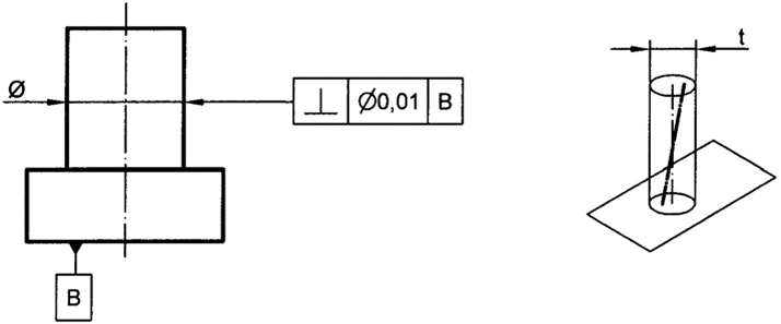
Figure 11
Figure 11. The axis of the controlled cylinder, the upper cylinder, must lie within a cylindrical tolerance zone of diameter 0,01 mm, and axis perpendicular to the reference plane B.
(d) The tolerance zone is defined by two planes parallel to each other, perpendicular to the reference plane and spaced -t- apart.
Figure 12
Figure 12. The area indicated by the tolerance rectangle must lie between two planes parallel to each other, spaced 0,05 mm apart, and perpendicular to the reference plane B.
19. Tilt tolerance
The tolerance zone is bounded by two parallel planes spaced -t- apart and inclined at the specified angle to the reference plane.

Figure 13
Figure 13. The inclined plane of the part must be between two planes parallel to each other, spaced 0.1 mm apart, and inclined at an angle of 25° to the reference plane A.
20. Position tolerance
The tolerance zone is limited by a cylinder of diameter -t-, the axis of which is at the exact theoretical position of the controlled straight line, when the tolerance value is preceded by the sign Ø.
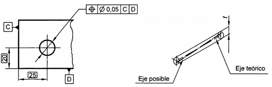
Figure 14
Figure 14. The axis of the bore must be inside a cylindrical tolerance zone of diameter 0,05 mm, the axis of which is in the exact theoretical position in relation to the reference planes C and D.
21. Coaxiality tolerance
The tolerance zone is limited by a cylinder of diameter -t-, the axis of which coincides with the reference axis, when the tolerance value is preceded by the sign Ø.
Figure 15
Figure 15. The axis of the cylinder indicated by the tolerance rectangle, the right one, must be inside a cylindrical tolerance zone of diameter 0,1 mm, coaxial with the reference axis, the left one.
Figure 16
Figure 16. The axis of the cylinder indicated by the tolerance rectangle, the centre one, must lie within a cylindrical tolerance zone of diameter 0,08 mm, coaxial with the reference axis A-B.
22. Symmetry tolerance
The tolerance zone is bounded by two parallel planes spaced -t- apart and placed symmetrically with respect to the reference symmetry plane (or axis).
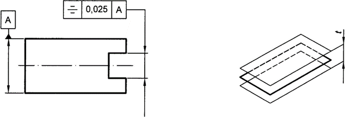
Figure 17
Figure 17. The plane of symmetry of the slot must be contained between two parallel planes spaced 0,025 mm apart and symmetrically placed with respect to the plane of symmetry specified by reference A.
23. Circular (radial) oscillation allowance
The tolerance zone is limited, within any plane of measurement perpendicular to the axis, by two concentric circles of radius difference -t- and centre coincident with the reference axis.
Figure 17.
Figure 17. The radial oscillation tolerance must not exceed more than 0,1 mm in any plane of measurement, for one complete revolution about the reference axis A-B.
24. Total oscillation tolerance (radial)
The tolerance zone is limited by two coaxial cylinders of radius difference -t-, whose axes coincide with the reference axis.
![]()
Figure 19
Figure 19. The total radial oscillation tolerance must not exceed 0,1 mm, at any point on the specified surface, during several revolutions about the reference axis A-B, and with relative axial movement between the part and the measuring instrument.